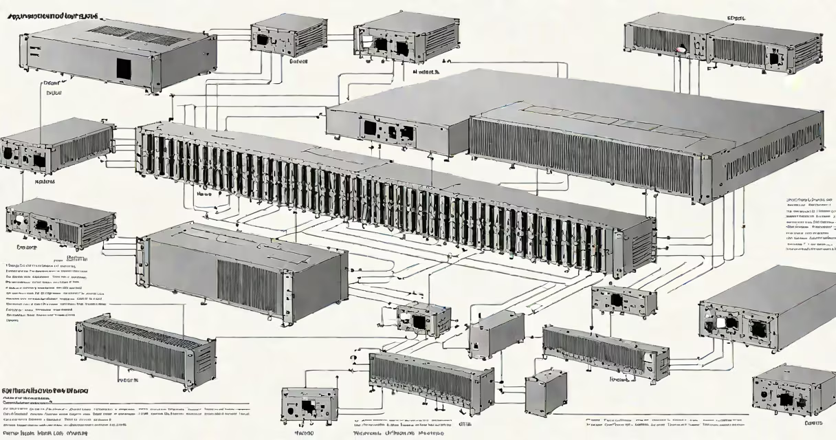
An aggregation switch is a high-capacity network switch deployed in data centers to collect traffic from multiple access switches and forward it toward the core network. It operates at Layer 3 in the OSI model, enabling routing between subnets and supporting advanced features like link aggregation, VLANs, and QoS. This switch sits between access switches and the core, reducing congestion and improving redundancy.
Aggregation switches handle large volumes of traffic from server racks, connecting hundreds of endpoints through lower-tier switches. They use high-speed uplinks-typically 10 Gbps or higher-to maintain low latency and high throughput. These switches are essential in environments requiring consistent performance under heavy load, such as cloud providers, financial institutions, and enterprise data centers.
According to Cisco's documentation on data center architecture, aggregation switches serve as the logical boundary between access and core layers, managing traffic flow and enforcing policies like bandwidth limits and security rules. Without them, core networks would face excessive strain from direct connections to numerous edge devices.
When a device in a server rack sends data, the access switch forwards it to the nearest aggregation switch. The aggregation switch evaluates the destination IP address, checks routing tables, and determines the optimal path to the core network. If the destination is within the same subnet, it may forward traffic locally. If not, it routes the packet through the appropriate uplink.
Aggregation switches use protocols like Spanning Tree Protocol (STP) and Link Aggregation Control Protocol (LACP) to prevent loops and increase bandwidth. For example, LACP allows multiple physical links between switches to act as a single logical connection, boosting throughput and providing failover capability. A single 10 Gbps port can be combined with another to create a 20 Gbps virtual link.
These switches also support Quality of Service (QoS) settings, prioritizing time-sensitive traffic such as VoIP or video streaming. A misconfigured QoS policy can lead to jitter or packet loss, but proper setup ensures real-time applications perform reliably even during peak loads.
Aggregation switches vary based on form factor, port density, and protocol support. Common types include modular chassis switches and fixed-port rack units. Modular switches allow expansion with additional line cards, ideal for growing infrastructures. Fixed-port models are simpler and cost-effective for stable deployments.
| Type | Port Density | Use Case | Speed Support |
|---|---|---|---|
| Fixed-port rack switch | 24-48 ports | Mid-sized data centers | 1 Gbps to 10 Gbps |
| Modular chassis switch | 64+ ports (expandable) | Large-scale cloud environments | 10 Gbps to 100 Gbps |
| Layer 3 managed switch | Varies | Routing between VLANs | Supports OSPF, BGP |
Key features include support for Virtual Router Redundancy Protocol (VRRP), which enables automatic failover if the primary router fails. This ensures continuous connectivity during outages. Aggregation switches also integrate with monitoring tools like SNMP and NetFlow, allowing administrators to track bandwidth usage and detect anomalies.
A non-obvious distinction: not all Layer 3 switches are aggregation switches. While both route packets, aggregation switches are designed for high availability, redundancy, and scalability. A typical desktop Layer 3 switch may have limited power, cooling, and failover mechanisms unsuitable for data center deployment.
Aggregation switches are standard in multi-rack data center designs. They reduce the number of direct connections to the core network, simplifying topology and minimizing configuration complexity. Instead of connecting every access switch to the core, only the aggregation switches do-cutting down on cabling and administrative overhead.
For example, a 10-rack data center might deploy ten access switches (one per rack), each connected to a single aggregation switch. That aggregation switch then links to the core via two 40 Gbps uplinks using LACP. If one link fails, traffic automatically reroutes through the other, maintaining service continuity.
Without aggregation switches, a core network would need to manage thousands of individual device connections. This leads to higher CPU usage, slower convergence times, and increased risk of broadcast storms. By centralizing traffic management, aggregation switches improve stability and simplify troubleshooting.
According to Juniper Networks' white paper on data center design, deploying aggregation switches reduces the number of routing entries in the core by up to 90%, lowering the burden on core routers and improving network responsiveness.
Many confuse aggregation switches with core switches. Core switches operate at the highest layer of the network hierarchy, handling inter-data center traffic and connecting multiple aggregation layers. Aggregation switches sit below the core and above access switches. Misplacing a switch in the wrong tier causes performance bottlenecks and inefficient routing.
Another mistake is assuming that any high-end switch qualifies as an aggregation switch. A switch with 48 ports and 10 Gbps speeds may be useful-but if it lacks redundant power supplies, fan modules, or support for advanced routing protocols, it cannot reliably serve as an aggregation node in a production environment.
I once observed a small business deploy a consumer-grade managed switch as an aggregation device. It handled basic routing but failed under sustained load due to overheating. After replacing it with a purpose-built aggregation switch, network latency dropped from 12 ms to 2 ms during peak hours.
Also, some assume that stacking switches eliminates the need for aggregation. Stacking combines multiple switches into a single logical unit, but it doesn't replace the function of an aggregation switch. Stacked access switches still require a dedicated aggregation layer to connect to the core.
Deploying an aggregation switch requires careful planning. Start by mapping the number of access switches and expected traffic volume. Estimate peak bandwidth demand using historical data or traffic modeling tools. Then select a switch with sufficient uplink capacity and redundancy.
Consider a university data center with 20 server racks. Each rack has 20 servers connected to an access switch. The total endpoint count is 400. Traffic from each rack averages 1 Gbps. Using four aggregation switches, each handling 100 devices, ensures balanced load distribution.
Each aggregation switch connects to two core switches via 10 Gbps SFP+ modules. STP is enabled to prevent loops. LACP bonds the two uplinks per switch, creating 20 Gbps effective bandwidth. VLANs are segmented by department-finance, research, IT-each with assigned QoS levels. Critical systems receive priority treatment during congestion.
Monitoring tools like SolarWinds or Zabbix track interface utilization. Alerts trigger when bandwidth exceeds 80% for five minutes. This proactive approach prevents downtime and identifies potential bottlenecks early.