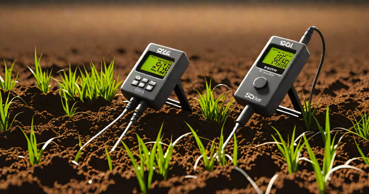
A soil resistance meter measures the electrical resistivity of soil to assess how effectively it can conduct fault current away from electrical systems, ensuring safety and compliance with grounding standards.
These instruments are essential for designing and verifying grounding systems in substations, telecommunications towers, and industrial facilities. They apply a known voltage between two electrodes inserted into the ground and measure the resulting current flow to calculate resistance. The most common method uses the Wenner four-electrode configuration, where four equally spaced probes are driven vertically into the soil.
Results are reported in ohm-meters (Ω·m), representing the soil's ability to dissipate electrical energy. A lower reading indicates better conductivity. For example, dry sandy soil may register 1,000 Ω·m, while moist clay can drop to 50 Ω·m. This variation directly affects the design of grounding grids and electrode spacing.
Soil resistance meters operate on the principle of Ohm's Law: resistance equals voltage divided by current (R = V/I). The device injects a test current through two outer probes and measures the voltage drop across two inner probes. By controlling distance and current magnitude, it calculates apparent resistivity using the Wenner formula:
ρ = 2πa × (V/I)where ρ is resistivity in Ω·m, a is the probe spacing in meters, V is measured voltage, and I is injected current. This equation accounts for soil layering and depth variations.
Modern meters automate calibration and temperature compensation. They often include data logging, GPS tagging, and Bluetooth connectivity for field reports. Some models support multiple configurations-Wenner, Schlumberger, and 3-point methods-to adapt to site constraints.
Soil resistance meters fall into two categories based on function and accuracy:
| Type | Use Case | Accuracy Range | Typical Output |
|---|---|---|---|
| Handheld Digital | Field testing, routine inspections | ±2% to ±5% | Resistivity (Ω·m), resistance (Ω) |
| Benchtop Precision | Laboratory analysis, engineering design | ±0.5% to ±1% | Multi-depth profiles, layered modeling |
Utility companies use handheld units during annual maintenance checks. For instance, a utility in Texas deployed a Fluke 1625-2 GEO meter to verify grounding integrity at a 138 kV substation. After detecting a localized high-resistance zone, they discovered a buried metal pipe interfering with electrode performance. Corrective action reduced ground resistance from 12 Ω to 3.2 Ω, meeting IEEE Std 80 requirements.
Engineers rely on benchtop models to create soil stratification maps. These tools simulate conditions across depths, helping predict long-term performance under wet/dry cycles. According to the National Fire Protection Association (NFPA), improper grounding contributes to 12% of electrical fires in industrial zones-making accurate measurements important.
Many assume that a single measurement gives a complete picture. In reality, soil resistivity varies with moisture, temperature, and seasonal changes. A reading taken in summer drought may differ by 300% from winter saturation. The International Electrotechnical Commission (IEC) standard 61000-4-5 recommends measuring at multiple times of year for reliable baseline data.
Another error is assuming uniform soil. Layered strata-such as a thin topsoil over bedrock-can produce misleading results if probe spacing doesn't match depth. Using a 1-meter spacing in a 3-meter-deep clay layer leads to underestimation. The correct approach involves testing at increasing spacings and plotting apparent resistivity against depth to identify layers.
I once observed a technician in Oregon use a 10-meter probe spacing on a site with shallow groundwater. Despite getting a low resistance value, the system failed during a lightning strike. Post-event analysis showed that the meter had averaged out a high-resistance surface layer. Switching to a 20-meter spacing revealed a deeper conductive zone missed earlier. This highlights why probe spacing must reflect expected depth of interest.
Soil resistance meters are not interchangeable with ground resistance testers. The latter measures the actual resistance of a completed grounding system-typically between a rod and remote earth. Soil resistance meters focus on material properties, not system performance.
For example, a ground resistance tester might show 2.5 Ω for a 3-meter rod in clay. That's acceptable per IEEE 80. But if the soil resistivity is 500 Ω·m, the rod's effectiveness drops sharply during dry seasons. Only a soil resistance meter reveals this vulnerability.
Soil resistance meters differ from multimeters. Multimeters measure circuit continuity or voltage but lack the current injection capability needed for earth testing. Attempting to use a multimeter for soil resistivity yields invalid results due to insufficient drive current and poor noise rejection.
Best practice involves taking at least five readings at different probe spacings (e.g., 1 m, 2 m, 5 m, 10 m, 20 m). Plotting apparent resistivity versus spacing generates a curve that identifies subsurface layers. A sharp rise suggests a resistive layer; a plateau indicates homogeneous material.
In a project at a wind farm in Iowa, engineers used a Megger Earth Tester 3124 to map soil resistivity across 12 turbine sites. Initial tests showed average resistivity of 200 Ω·m. However, after expanding spacing to 25 meters, one site revealed a 5-meter-thick sand layer beneath 1 meter of topsoil. Without adjusting electrode depth, the grounding system would have failed under lightning surge conditions.
Based on the data, they increased rod length from 3 m to 6 m and added radial conductors. Final verification confirmed ground resistance below 5 Ω-within the 5 Ω limit specified in the project's design manual. This outcome was only possible because the team used proper spacing and interpreted the resistivity profile correctly.
Soil resistance meters are not optional-they're required for safe, compliant electrical infrastructure. Their outputs inform design choices, validate installation quality, and prevent hazards from ground faults and lightning strikes.