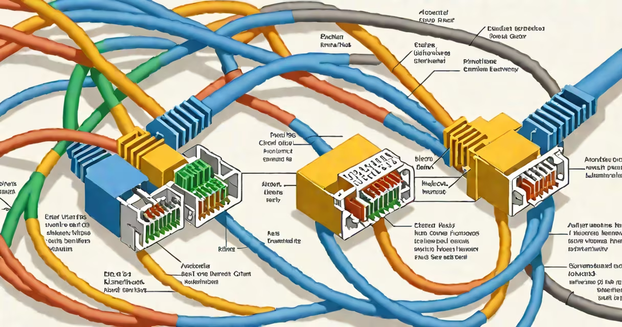
A cat 5e rj45 wiring diagram specifies the exact order of eight individual copper wires inside a twisted-pair Ethernet cable, arranged to connect devices via standard RJ45 connectors. The diagram defines both straight-through and crossover configurations used in networking.
Each wire in a cat 5e cable is color-coded and twisted in pairs to reduce electromagnetic interference. The standard pinout for a straight-through cable assigns specific colors to pins 1 through 8 on the RJ45 connector. This ensures consistent signal transmission between network devices like computers, routers, and switches.
The most common application is connecting a computer to a switch or router using a straight-through cable. A crossover cable, which swaps transmit and receive pairs, was historically used to connect similar devices directly-such as two computers-but modern network interfaces auto-detect and adjust for this, making crossover cables largely obsolete.
Inside a cat 5e cable, four pairs of insulated wires are twisted together. Each pair carries differential signals to minimize crosstalk and noise. When terminated with an RJ45 connector, the wires are arranged in a precise sequence based on the T568A or T568B standard.
For a straight-through cable, both ends follow the same wiring standard-typically T568B. This helps pin 1 on one end connects to pin 1 on the other, maintaining signal integrity across the link. Devices expect this mapping because they rely on consistent pin assignments for data transmission.
When a device sends data, it uses pins 1 and 2 for transmission, and pins 3 and 6 for reception. If both ends of a cable use the same standard, the transmit pair on one side aligns with the receive pair on the other. This alignment prevents communication failure.
Two standardized wiring schemes define how wires are assigned to pins: T568A and T568B. Both meet the same performance requirements but differ in wire placement. Only one standard should be used per cable run to avoid confusion and ensure compatibility.
| Pin | T568A Color | T568B Color |
|---|---|---|
| 1 | White/Green | White/Orange |
| 2 | Green | Orange |
| 3 | White/Orange | White/Green |
| 4 | Blue | Blue |
| 5 | White/Blue | White/Blue |
| 6 | Orange | Green |
| 7 | White/Brown | White/Brown |
| 8 | Brown | Brown |
Most installations use T568B due to its prevalence in commercial settings. The difference lies in the position of the green and orange pairs. Using mixed standards on a single cable causes signal misalignment and results in failed connections.
For crossover cables, one end uses T568A and the other uses T568B. This swaps transmit and receive pairs, allowing direct communication between two devices of the same type. However, auto-MDI-X technology in modern NICs detects the connection type and adjusts automatically, eliminating the need for crossover cables in most cases.
cat 5e rj45 wiring diagrams are essential for installing structured cabling in homes, offices, and data centers. They ensure reliable gigabit Ethernet speeds up to 1 Gbps over distances up to 100 meters.
Network administrators use these diagrams during cable termination to verify correct pin assignment. A single miswired pair can cause intermittent connectivity, reduced throughput, or complete failure. Tools like a cable tester validate continuity and wiring accuracy after termination.
For example, when installing a new office network, a technician terminates both ends of a cat 5e cable using T568B. After crimping the RJ45 connector, they plug the cable into a switch and a desktop PC. The link lights turn green, confirming successful communication. Without proper wiring, the connection fails even if the cable appears intact.
One frequent error is mixing T568A and T568B standards on both ends of a cable. This creates a crossover effect unintentionally. For a straight-through cable, both ends must match the same standard.
Another mistake is improper stripping of insulation. Exposing too much wire increases crosstalk and reduces signal quality. The recommended exposure is 10-12 mm from the connector's edge. Leaving excess conductor exposed can cause short circuits or poor contact.
Non-obvious fact: The blue and white-blue pair (pins 4 and 5) is not used in 10/100 Mbps Ethernet but is critical for Gigabit Ethernet (1000BASE-T), which uses all four pairs simultaneously. Miswiring these pairs can result in a link that fails at high speeds despite working at lower rates.
I once encountered a client whose network worked at 100 Mbps but dropped to 10 Mbps under load. Testing revealed that the blue pair was reversed at one end. Correcting the wiring restored full gigabit performance. This issue wasn't caught during initial testing because the device defaulted to slower speeds.
Modern networks rarely require crossover cables. Auto-MDI-X allows network interface cards to detect whether a connection is straight or crossed and adjust accordingly. This feature is enabled by default on most hardware manufactured after 2005.
However, understanding the difference remains useful for troubleshooting legacy systems or configuring specialized equipment like industrial controllers or older switches.
Use a straight-through cable when connecting dissimilar devices: PC to switch, router to modem, or switch to hub. Use a crossover cable only when connecting two similar devices directly-like two PCs or two switches-without a central switch.
For most users, sticking to T568B and straight-through cables avoids complexity. If you're building a test lab or setting up a peer-to-peer connection, a crossover cable may still be necessary.
Suppose you need to connect a laptop to a network switch using a custom-made cat 5e cable. Follow these steps:
If the tester shows a fault on pin 3, check for bent or misaligned wires. Re-crimp and retest until all indicators pass.