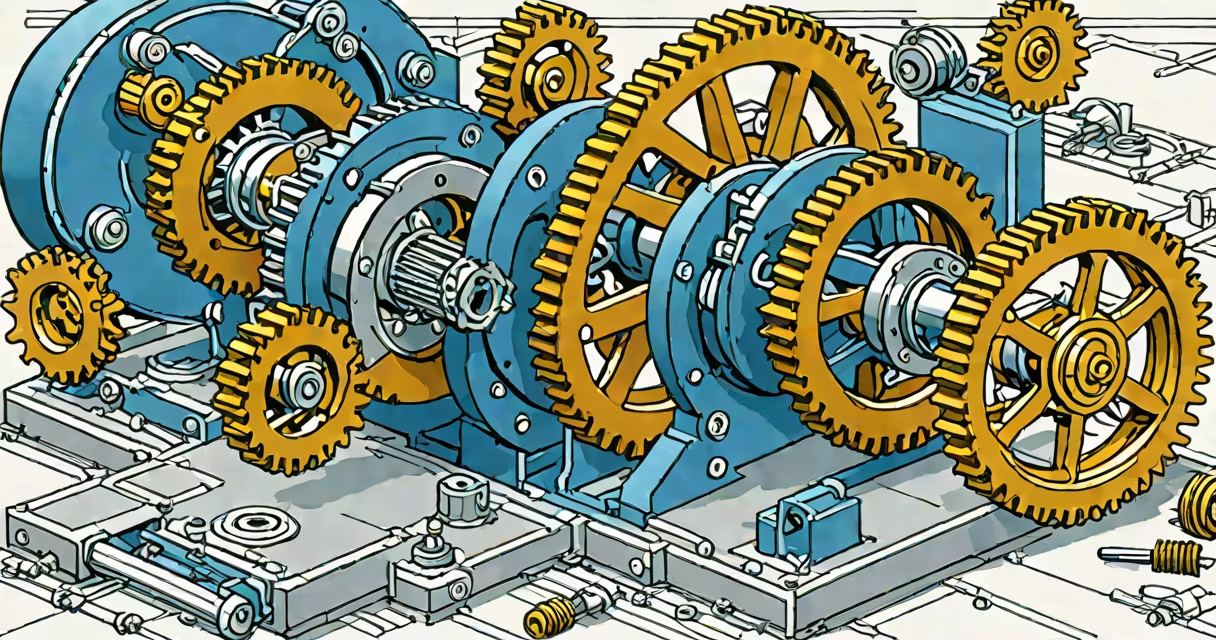
mechanical engineering drafting and design produces accurate, standardized technical drawings that communicate how mechanical components and systems are built, assembled, and function. These documents serve as the primary language between engineers, manufacturers, and fabricators during product development.
These drawings define dimensions, tolerances, materials, surface finishes, and assembly sequences using industry-standard symbols and notation. They originate from conceptual sketches and evolve through iterative refinement until they meet functional, safety, and manufacturability requirements. The output is a set of deliverables that enable physical production with minimal ambiguity.
According to the American Society of Mechanical Engineers (ASME), the Y14.5 standard governs geometric dimensioning and tolerancing (GD&T) in mechanical drawings. This ensures consistency across global supply chains. Without adherence to such standards, even minor deviations in part geometry can cause system failure.
Design begins with a problem statement-an identified need or performance requirement. Engineers use brainstorming, simulation tools, and prototyping to explore solutions. Once a viable concept emerges, it moves into formal drafting.
Drafting involves creating 2D orthographic projections (front, side, top views) and 3D models using computer-aided design (CAD) software. A single component may require multiple views, section cuts, and detailed annotations to convey all necessary information. Dimensions are applied precisely, often referencing datums established in GD&T.
After initial creation, drawings undergo peer review and approval. Revisions are tracked via revision control systems. Finalized drawings are released to manufacturing, where machinists and welders interpret them to produce parts. Any discrepancy between drawing intent and actual part results in rework or rejection.
Modern mechanical engineering drafting relies on digital tools rather than hand-drawing. CAD platforms like AutoCAD, SolidWorks, and Autodesk Inventor allow for parametric modeling-where changes to one feature automatically update related geometry.
Common elements in a mechanical drawing include:
A single drawing file may contain hundreds of annotations. For example, a bolt hole pattern in a flange might specify 8 holes at 120° intervals, with a diameter tolerance of ±0.05 mm and a positional tolerance of 0.1 mm relative to a datum plane.
There are two primary categories of mechanical engineering drafting and design: detail drawings and assembly drawings.
| Type | Purpose | Example |
|---|---|---|
| Detail Drawing | Defines a single part's geometry and manufacturing specs | Shaft with keyway, fillets, and surface finish Ra ≤ 1.6 µm |
| Assembly Drawing | Shows how multiple parts fit together and interact | Motor housing with bearing, shaft, seal, and mounting bolts |
Detail drawings focus on precision. They include all dimensions needed for machining, inspection, and quality control. Assembly drawings emphasize spatial relationships and functional sequence. They often show exploded views and bill of materials (BOM).
For instance, a hydraulic cylinder assembly drawing includes the barrel, piston, rod, seals, and end caps. It specifies the clearance between the piston and bore (typically 0.005-0.010 inches) and the preload on the seals to prevent leakage. Without this level of detail, the cylinder would fail under pressure.
Many assume drafting is purely visual or artistic. In reality, it is a technical communication discipline rooted in physics, materials science, and manufacturing constraints. A drawing is not a sketch-it is a legally binding document in many industries.
Another misconception is that CAD replaces engineering judgment. Software automates geometry creation but cannot assess whether a design will survive stress, fatigue, or thermal cycling. An engineer must still validate load paths, material behavior, and failure modes.
For example, a designer once created a gear shaft with a 1-inch diameter and a 0.25-inch keyway. The CAD model showed no interference. But upon simulating torsional loading, the stress concentration at the keyway root exceeded yield strength. The solution required changing the keyway profile and adding a fillet-adjustments that only a trained engineer would recognize as necessary.
In 2021, a team at a medical device manufacturer developed a new surgical instrument handle. The goal was to reduce weight while maintaining rigidity. Initial designs used aluminum alloy 6061 with a hollow cross-section.
The drafting phase included:
During CNC machining, a batch of handles failed inspection due to inconsistent wall thickness. The root cause was traced to a missing tolerance on the internal radius. The original drawing specified "R0.5" but omitted a tolerance. The machine tool interpreted this as absolute, leading to oversizing in some parts.
This error was corrected by adding a ±0.1 mm tolerance to the radius. The revised drawing prevented further defects. The incident illustrates how small omissions in drafting lead to costly failures-even in high-precision fields.
Every mechanical product-from automotive transmissions to wind turbine blades-depends on accurate drafting and design. Errors in documentation result in defective parts, delays, recalls, and liability. According to NIST, poor design documentation costs U.S. manufacturers $15 billion annually in rework and waste.
Compliance with ISO 129 (technical drawings - representation) and ASME Y14.5 ensures interoperability across international teams and suppliers. A drawing made in Germany must be interpretable by a shop in Texas without confusion.
Understanding mechanical engineering drafting and design is essential for anyone involved in product development. It bridges imagination and reality, turning ideas into functional, safe, and buildable hardware.
With the right training and adherence to standards, mechanical engineering drafting and design enables innovation at scale. It is not just about lines and numbers-it is about precision, responsibility, and execution.
Mastering mechanical engineering drafting and design means mastering the foundation of engineered systems. From concept to construction, it defines what gets built-and how well it performs.